Making doors look right in different ortho views
While I was putting together this post last month, it dawned on me that doors are represented differently in plan, elevation and sectional orthographic views of a building. By which I mean:
- In plan, doors are generally shown in the open position.
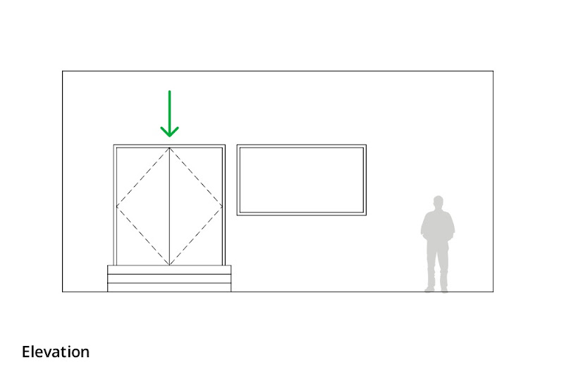
- In elevation, doors appear closed.
- When cut through in section, doors disappear altogether.
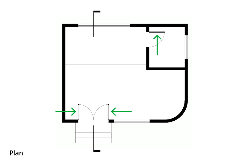
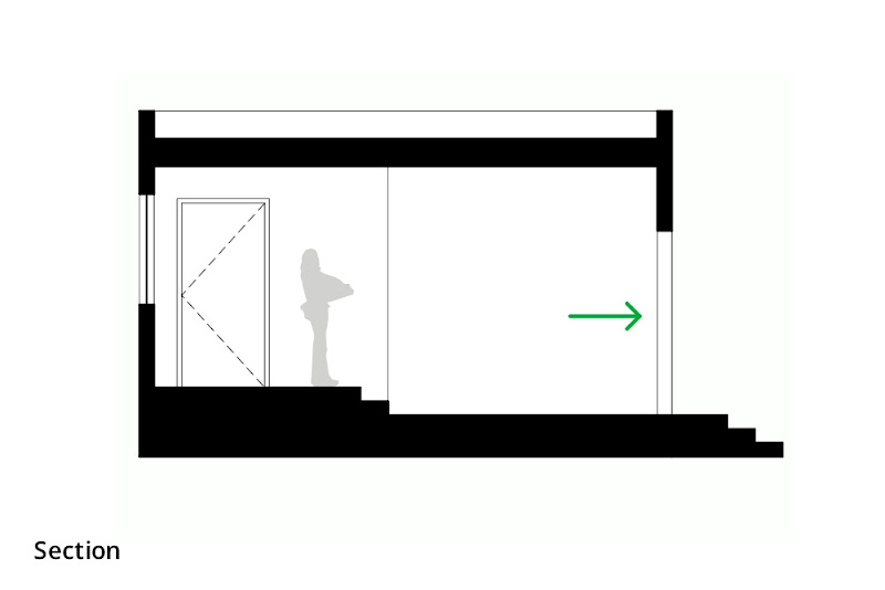
In plan, doors appear open to show their swing. In the above image, the swing arcs, section cut graphics and arrows were added in LayOut.
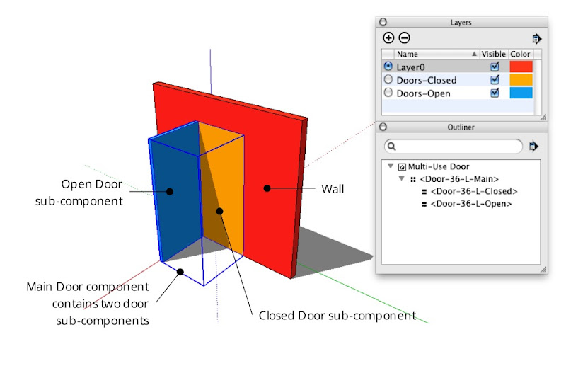
If I’m modeling a building and I leave the doors open, they’ll look correct in plan but not in other views. If I close them, the plans will look wrong. Clearly, I need two sets of doors—one open, one closed—and I need to manage which set is visible in each view. Layers, Scenes and nested components to the rescue!
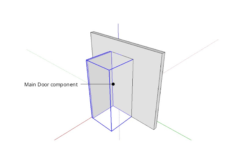
The idea here is to create a door component that includes two sub-components: one that’s an open door, and one that’s a closed door. Mine looks something like this:
Creating a combination door component
Start by modeling both doors and turning them into a set of nested components:
Step 1
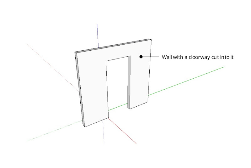
Create the hole into which you want to insert a door.
Step 2
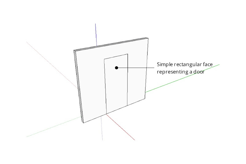
Model a door in the closed position. Keep it simple; a rectangle is fine for now.
Step 3
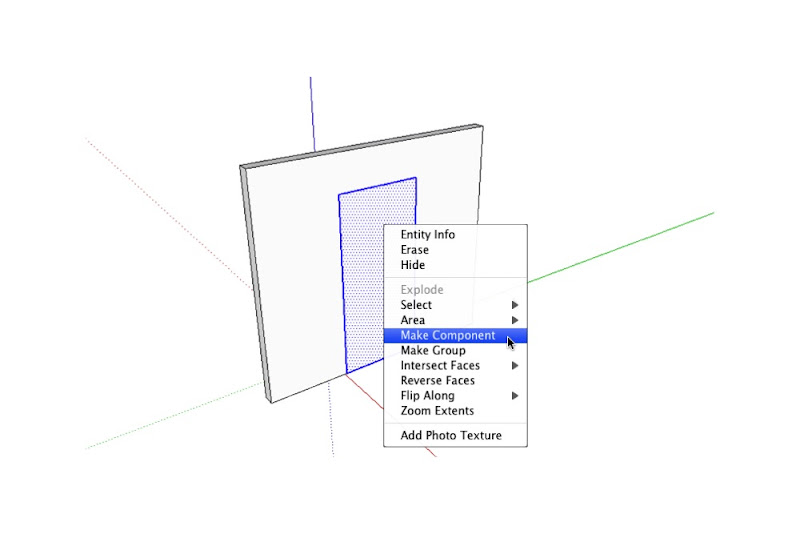
Select only the door geometry and turn it into a component. Give it a meaningful name that describes its size, orientation and position like “Door-36-L-Closed”.

Step 4
If you like, add detail (like a thickness) to the door you just modeled.

Step 5
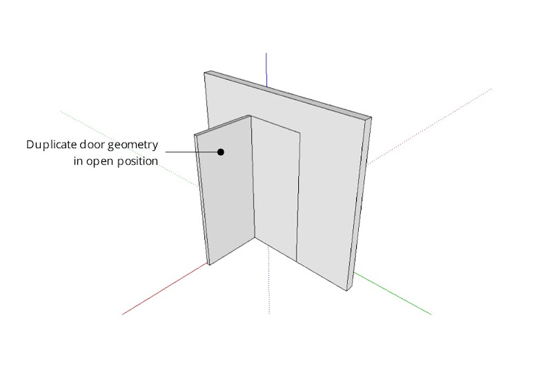
Model the same door in the open position. Be sure not to duplicate the component instance you made in the previous step — the whole point of this exercise is to have two, separate components.
Step 6
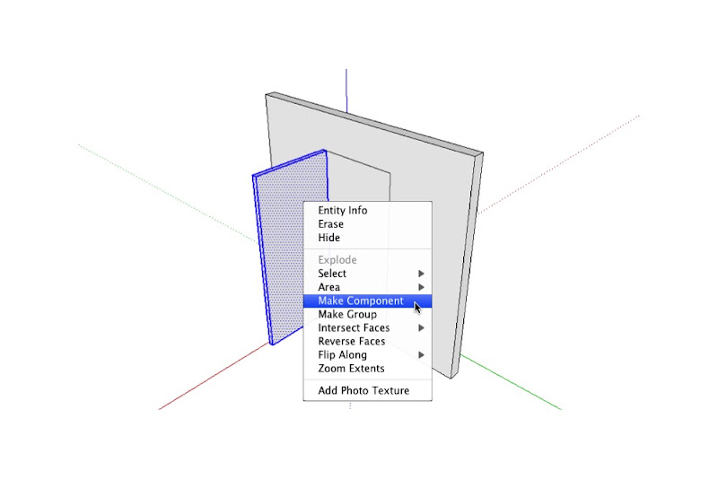
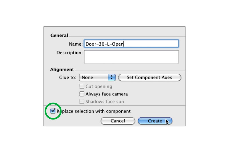
Turn the open door into a new component. Call it something like “Door-36-L-Open”.
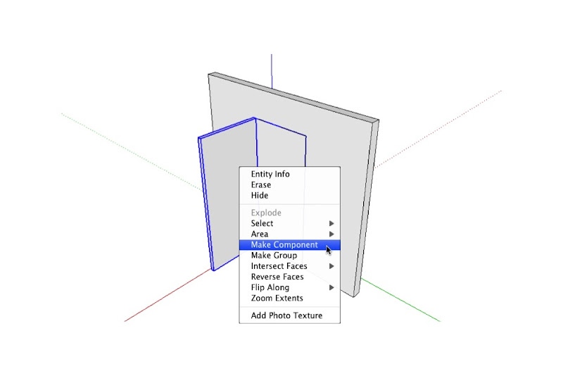
Step 7
Select the open and closed door components and make a new component that includes both. A good name for this component might be “Door-36-L-Main”.

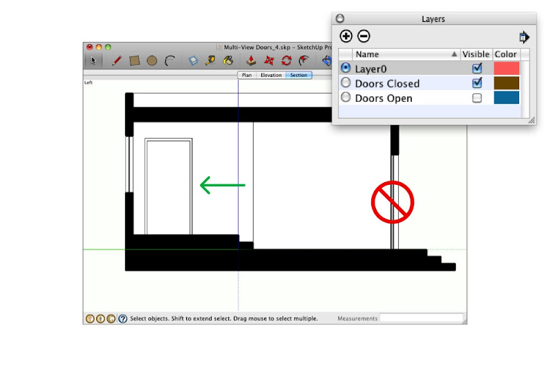
Using Layers to control component visibility
The next step is to put each sub-component on a separate layer:
Step 1
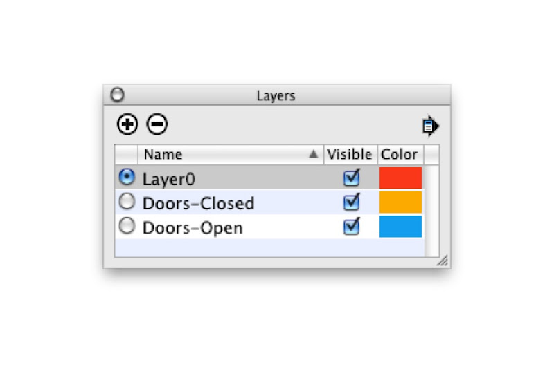
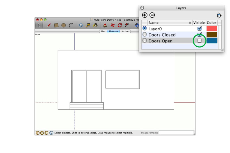
Choose Window>Layers to open the Layers Manager.
Step 2
Create a new layer called “Doors-Open”.
Step 3
Create another layer called “Doors-Closed”.
Step 4
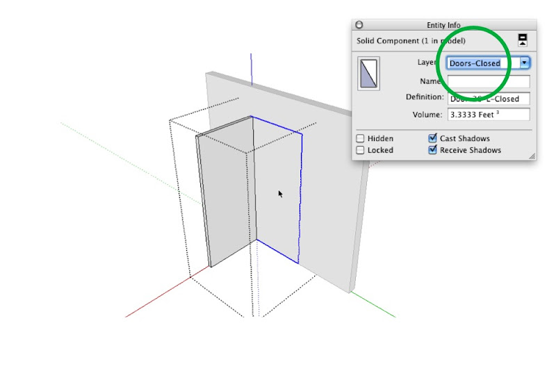
Choose Window>Entity Info to open the Entity Info dialog box.
Step 5
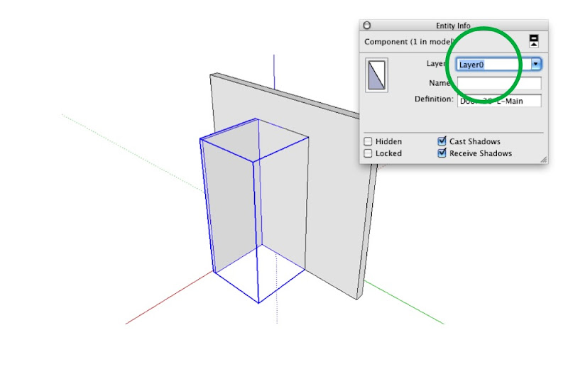
Start editing your Main door component (the one that includes both sub-components) by double-clicking it with the Select tool.
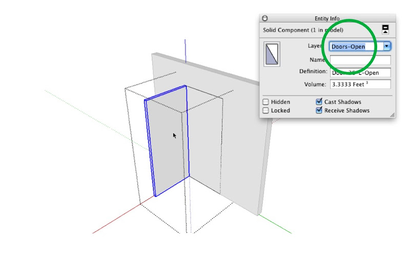
Step 6
Select the closed door sub-component and move it to the “Doors-Closed” layer using the Layer drop-down menu in the Entity Info dialog box.
Step 7
Select the open door component and move it to the “Doors-Open” layer.
Step 8
Click elsewhere on your screen to stop editing the Main door component.
Setting up Scenes to control layer visibility
After you’ve placed doors wherever you need them in your model, you can control which set is visible by creating (or updating) scenes that show only one “Doors” layer at a time. It’s pretty straightforward, really:
Step 1
Activate the scene that corresponds to a plan view of your model. If you don’t have one yet, just create a new scene called “Plan” and worry about getting the camera position in order later.
Step 2
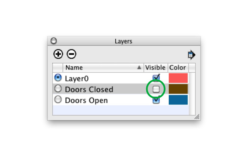
In the Layers Manager, hide the “Doors Closed” layer.
Step 3
Right-click the “Plan” scene tab and choose Update.
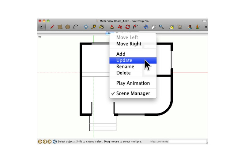
Step 4
Repeat the above three steps for any other planimetric scenes in your model.
Step 5
Go through the above process again for any scenes where doors should appear closed.
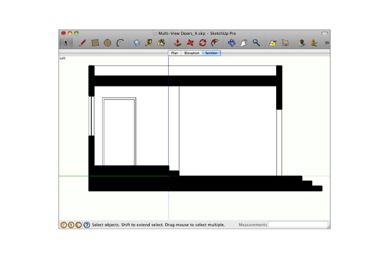
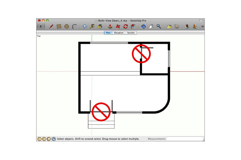
Dealing with doorways in section
What about doors that are cut through by section cuts? They shouldn’t appear at all. The solution here is simple: Just hide the offending door components and update your scene.